Welcome, Guest
Username: Password: Remember me

TOPIC: 1963 Glastron V143 JetFlite Restoration

Re:1963 Glastron V143 JetFlite Restoration 11 years 1 month ago #86048

  • Shake
  • Shake's Avatar
  • Offline
  • Gold Boarder
  • Gold Boarder
  • Posts: 983
  • Karma: 29
  • Thank you received: 6
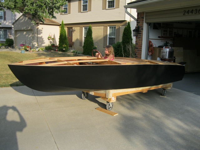
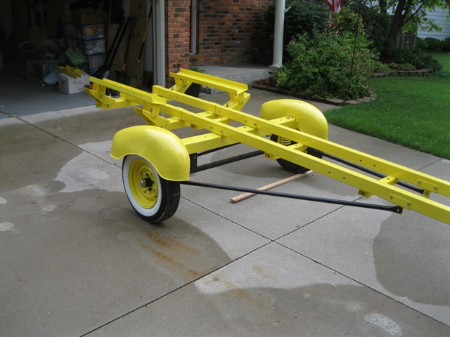
WOW!!! This boat is amazing, keep up the good work kern! also great choice in color, she really pops!

Please Log in or Create an account to join the conversation.

Golden Rule number one; While working in the bilge, absolutely under no circumstances, NO FARTING!!!! Captn Shake aka Joe.

Re:1963 Glastron V143 JetFlite Restoration 11 years 1 month ago #86115

  • Kern
  • Offline
  • Junior Boarder
  • Junior Boarder
  • Posts: 105
  • Karma: 17
  • Thank you received: 1
Captain Shake - thank you for the compliments. The color chosen is quite close to the original gel coat color. We picked an upholstery color that was as close as we could get to the original gel coat and then picked the paint color to match the upholstery.

The paint color was chosen by the first restoration shop that I used and it is a standard automotive color for an Isuzu. It looks to be slightly different than the upholstery color but that may be due to a difference in texture of the surfaces. When all the pieces come together we will see the overall result.

Please Log in or Create an account to join the conversation.

Re:1963 Glastron V143 JetFlite Restoration 11 years 1 month ago #86153

  • 63 Sabre
  • 63 Sabre's Avatar
  • Offline
  • Contributing Member
  • Contributing Member
  • Posts: 4676
  • Karma: 147
  • Thank you received: 167
Geeze man, first class all the way, amazing job so far. Can't wait to see the final finished project.
Cal

Please Log in or Create an account to join the conversation.

Re:1963 Glastron V143 JetFlite Restoration 11 years 1 month ago #86218

  • Kern
  • Offline
  • Junior Boarder
  • Junior Boarder
  • Posts: 105
  • Karma: 17
  • Thank you received: 1
Work proceeds on several aspects of the project, including reinforcing the transom, the floor structure, the foredeck support structure, and the seats. To make it easier for everyone to see what is done in each of these areas, a chronological narrative is being abandoned in favor of a subject narrative. Pictures will be taken of progress in each area and when that area is finished, the pictures and description of the process will be presented complete. This should make it easier for the reader to follow the restoration/rebuild/update.

FLOTATION

The rarity of this boat combined with the cost and effort being expended on the restoration lead to the conclusion that there was no way it was ever going to be allowed to sink.

As delivered, there were planks of rigid foam under the foredeck and some bags of flotation beads under the floor between the stringers. This combination did not provide enough flotation to keep the boat from sinking in case of an incident.

The weight of the boat as noted in the factory information was just shy of 500 pounds. The addition of the motor, battery, and other gear probably adds another 200 pounds. Allowing some additional margin for safety, a total of about 800 pounds of flotation capacity is being planned. This works out to about 13 1/3 cubic feet of flotation volume.

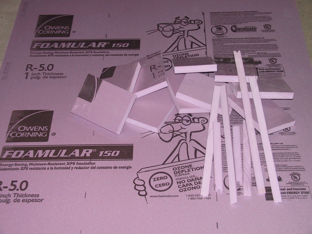
Various flotation means can be considered, from the ridiculous (helium balloons?) to the sublime. The most cost effective is probably rigid, closed cell foam. This can be the chemical expanding type (Great Stuff) or rigid foam planks or sheets. I had some foam sheets on hand for a home project so decided to experiment with them. It is Owens Corning pink insulating foam. It comes in 4 X 8 foot sheets in various thicknesses and is available at modest cost at builder supply stores.

To insure that this foam would be suitable for this purpose and installation, I performed two tests. I took small samples and submerged one in water for several days to see if it would absorb any water - it did not. I took another sample and coated part of it in epoxy resin to see if there would be any chemical reaction that would affect the foam - there was not. I did not try a sample with polyester resin so cannot comment on that compatibility.

A sheet of the foam being used along with some parts that were cut to fit. The strips are 1/4 X 1 inch and were cut from the edge of a sheet. They are being used to fill a shallow cavity in the underside of the foredeck.

I chose to use the one inch thickness as it provides slight flexibility and reasonable volume. It can be easily cut and shaped to fit within various cavities. Each sheet provides 2 2/3 cubic feet of volume, or about 160 pounds of flotation. Installation will involve placing foam into various available cavities and filling them as effectively as possible, especially near the stern where much of the weight is concentrated. This will involve a lot of cutting and fitting and will be quite labor intensive. When being installed, each piece will be coated with epoxy to bond it to surrounding surfaces and minimize any voids where moisture (and mold) can collect. Bonding the foam in place will also aid the rigidity of the hull.

A NEW DESCRIPTION

With all the thought and work that is going into this project to do it the best we can, I have a new description that has come to mind to refer to this boat:

THE FOREVER BOAT - meaning it is being rebuilt to last forever with only cosmetic updates and/or restoration required.
Attachments:

Please Log in or Create an account to join the conversation.

Re:1963 Glastron V143 JetFlite Restoration 11 years 1 month ago #86235

  • 63 Sabre
  • 63 Sabre's Avatar
  • Offline
  • Contributing Member
  • Contributing Member
  • Posts: 4676
  • Karma: 147
  • Thank you received: 167
It's easy to make perfect fit foam blocks out of that stuff. Cut several pieces slightly larger than the void you're going to fill, epoxy them together to make a block and you can simply sand them into a perfect fit using a 40 grit paper or a cheese grater.

Please Log in or Create an account to join the conversation.

Re:1963 Glastron V143 JetFlite Restoration 11 years 1 month ago #86481

www.fiberglassics.com/media/kunena/attachments/legacy/images/IMG_0030-20131018.JPG

Do you have any other pictures of the bow mount for your rotisserie? I'm looking to design something similar for my 64 Johnson deluxe.

Please Log in or Create an account to join the conversation.

Re:1963 Glastron V143 JetFlite Restoration 11 years 1 month ago #86652

  • Kern
  • Offline
  • Junior Boarder
  • Junior Boarder
  • Posts: 105
  • Karma: 17
  • Thank you received: 1
Apologies for the slight delay in response. I have been traveling and was not checking my postings.

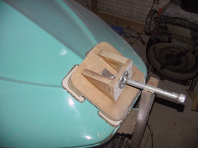
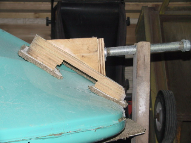
I did not take any pictures of the pivot mounts prior to attaching them to the boat. I did take some additional pictures of the front mount in place and these are included, along with a more thorough description. In these pictures, the boat is inverted so the pictures are taken from above.

I will provide data regarding details of my mount. Anyone building a similar mount for their boat will probably have to change some of the dimensions to suit the shape of their hull, and may have to change the strength of the mounts if their hull is heavy. My hull has a factory specified weight of about 500 pounds and when I add my weight and tools, etc. the total gets close to 700 pounds.

The support posts are 2X4 with triangular ¾ plywood legs attached to all four sides at the bottom. A vee notch was cut into the top of the post to locate the pivot pipe. For heavier or larger hulls, the support posts can be made more elaborate with larger bases and more strength.


All the wood parts of the mount are cut from ¾ plywood. The large piece (main plate) is 12 X 12 inches with rounded corners. The larger this main plate, the greater will be the spread of the loads into the hull, with less chance of deformation or damage.

At each corner is a triangular shaped spacer block, which is two layers of plywood. These were then shaped on the surface that contacts the hull so that the contact area is maximized. A hole was drilled through the center of the main plate for the stud that goes through the bow eye mounting hole.

The spacers have to be tall enough that when the main plate mounting stud is tightened there will still be a slight gap between the main plate and the hull. This will insure that the loads on the hull are spread to a minimum of three areas at all times – the main plate stud and at least two corner spacers. The load at the stud will be in tension and the corner spacers will be in compression.

Soft, thick carpet pieces were used to pad the spacer blocks and the main plate against the fresh paint of the hull. These are glued in place on the pivot mount so they will not fall out during installation or use.

After the main plate could be attached to the hull for a trial fit, a protractor was used to determine the angle of the main plate relative to a vertical reference plane. This angle was used to define the shape of the side parts of the front mount. The face plate of the front mount has to be large enough to accept a standard pipe flange. The side plates are glued and screwed to the main plate and the front plate is glued and screwed to the side plates. The corner spacer blocks only need to be glued to the main plate as they are not in tension.

You do not want any part of this to fail during work on the hull!!!

A pipe flange was bolted through the front plate with through bolts backed up by steel strips to spread the loads over a large area of the front plate. The pipe fittings I used are ¾. The nipple is 10 inches long, the cap is to provide a rounded end and provide a stop to prevent the pipe from sliding out of the support post, although this has not proven to be an issue.

Inside the hull, the area where the bow eye stud comes through was reinforced with a temporary steel plate to spread the loads over as large an area as possible. The support posts should be kept as close to the pivot mounts as possible to minimize the bending loads on the mounts. When determining how close to place the support posts, rotate the hull through a full roll to check for clearances to the support posts, the floor, and the ceiling.

In the profile picture, it can be noted that the pipe nipple is not horizontal and is sagging slightly at the hull end. This is primarily due to compression of the carpet pads at the corner blocks and is not indicative of a pending failure. I have been working inside the boat with the hull at various angles and the whole system is quite stable.
Attachments:

Please Log in or Create an account to join the conversation.

Re:1963 Glastron V143 JetFlite Restoration 11 years 1 month ago #86654

Awesome reply, thanks for taking time to give me a wealth of information. It will be challenging to apply this to my Deluxe. The hull weighs 1000-1200 pounds at this time. Also, the bow eye is set pretty far back, at least 10-12 inches with steep compound angles around it. You photos and description are a huge help to me, thank you so much for sharing.

Please Log in or Create an account to join the conversation.

Re:1963 Glastron V143 JetFlite Restoration 11 years 2 weeks ago #87340

  • Kern
  • Offline
  • Junior Boarder
  • Junior Boarder
  • Posts: 105
  • Karma: 17
  • Thank you received: 1
Work continues on the hull in the partially heated work area along with various inside projects.

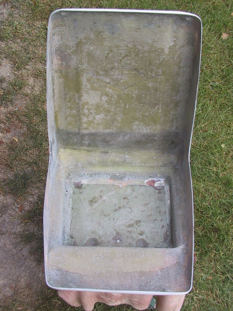
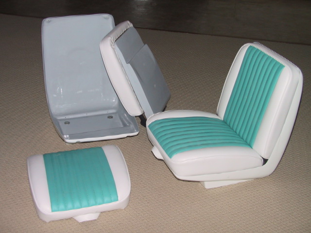
As received from City Auto Body the outsides of the seat shells were finish painted and were beautiful. The insides were as molded and were rough and multicolored. The insides were sanded to prepare them for a coat of epoxy. This was sanded relatively smooth for painting. The bottom board of the seats was also cut out and replaced by a larger board that filled the entire width of the bottom to spread the loads and eliminate the side channels.

The inside of one of the seat shells showing the rough interior surface and the bottom board that was not full width.

The inside of the shell has been sanded to eliminate most of the roughness. The bottom board has not been cut out yet.

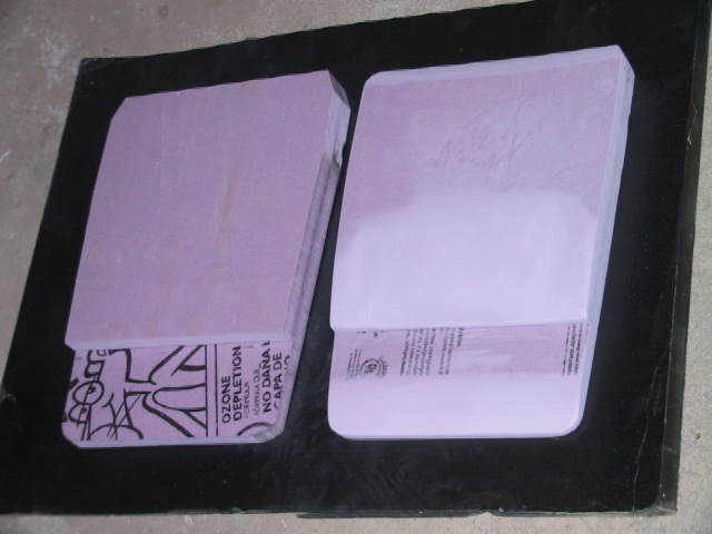
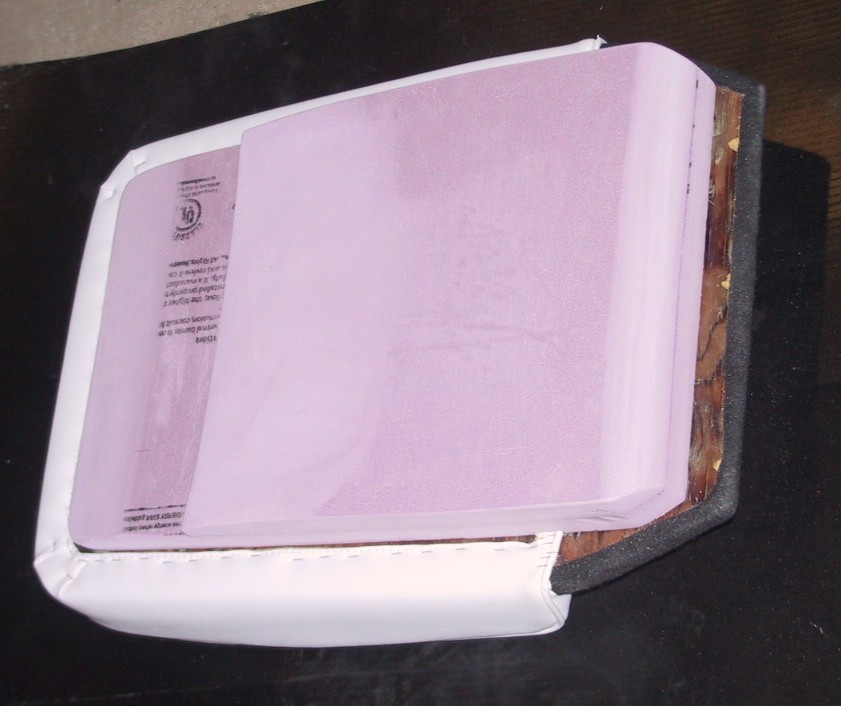
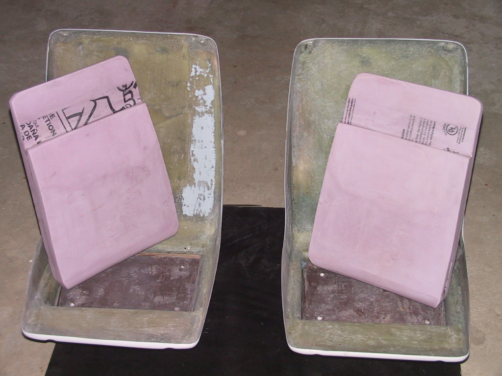
It was noted that there was a large cavity between the seat backrest board and the inside of the seat shell. If the boat was swamped, this volume would fill with water and contribute nothing to flotation so foam inserts were made to fill most of the cavity. Each of the inserts will contribute about 10 pounds of flotation to the boat.

The foam inserts for the seat backs. The one on the left is as cut and bonded with epoxy. The right has been shaped and sanded to fit within the cavity.

Trial fitting the foam insert to the back of the backrest.

The seat shells after sanding and epoxy coating - ready for painting.

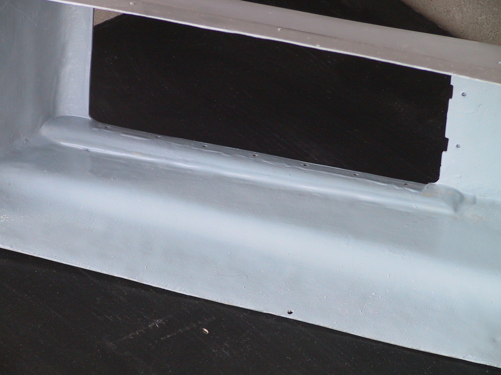
The insides of the seat shells and the foam inserts were painted with a gloss grey marine paint that will also be used on the inside of the hull. This will provide a consistent color that will be easy to keep clean.

The original seat hold downs were two screws on the seat centerline with toggle type anchors in the floor. Over time, corrosion froze the parts together so the anchors had to be torn from the floor to be replaced. The stresses from only two attachments also showed on the seat bottoms.

The new mountings are four per seat and are made of brass. Brass was used rather than stainless steel because the brass parts are easier to fabricate by brazing. The floor anchor plates are attached by four screws and epoxy. They have a nut brazed to the bottom. The hold down screws were made by brazing a rod to the head of a slotted machine screw, forming a wing screw, for easy tightening and removal by hand.

The holes in the seat base boards have brass tubes bonded inside them to seal the wood and prevent any movement from wearing the wood. The washers are bonded in place with a couple of silicone seal spots to prevent having to keep track of them when the screws are removed.

The mounting hardware that will be used for each seat.

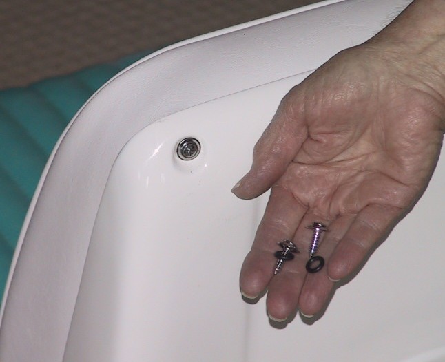
Each seat backrest is held in the shell by five screws. Chrome trim screws with integral formed washers were chosen for this purpose. The formed washers have a sharp edge that would dig into the new paint. O-rings were selected that would fit under the washers and help to cushion the washer and protect the paint.

The trim screws used to hold the backrest cushions in place.

Please Log in or Create an account to join the conversation.

Re:1963 Glastron V143 JetFlite Restoration 11 years 2 weeks ago #87341

  • Kern
  • Offline
  • Junior Boarder
  • Junior Boarder
  • Posts: 105
  • Karma: 17
  • Thank you received: 1
The foam inserts are attached to the backrest boards by several silicone seal dots. This will facilitate later removal, if necessary.

The original seats had a trim strip around the top of the shell surrounding the backrest. After fitting the new backrests into the shells, the appearance was very finished looking and this trim was deleted. The completed seats have what is felt to be a more upscale look than the originals. They also cost a lot more, in both money and time!!
Attachments:

Please Log in or Create an account to join the conversation.

Re:1963 Glastron V143 JetFlite Restoration 11 years 2 weeks ago #87344

Hey Kern, those seats are gorgeous! Great work

Please Log in or Create an account to join the conversation.

Re:1963 Glastron V143 JetFlite Restoration 11 years 2 weeks ago #87352

Kern,

Just read your post. Looks like your project is almost toward the end. Great job and keep up bad part now is you have to wait out the winter. I do have some concerns with your remarks on Starboard Marine Restoration and if you have issues with them keep that private and not throw it out on the web for everyone to see and make judgement without knowing the facts. I no nothing of this project until I read your post today. Do you even have a clue of the knowledge and skills that Dick has learned over the years? Anyway enought of that I think you know where I'm going with this. Boat looks great hopefully you'll have it done and enjoy! I attached a pick of my 63' Power Cat will start this project summer of 14' and due to me doing all work will take about a year and a half. Once I get it going we'll have to "Run Em" and see if that JetFlite will keep up.

Pondrocket
Attachments:

Please Log in or Create an account to join the conversation.

www.liquidassetsonline.org , 63\'PowerCat14-C w/twin64\'650\'s,14\'Glen-L Zip w/Mark58E,58\'TeeNee,
Mark55AE,Mark55E,PairMark58E\\\'s,Mark58AE,Mark78AEL, 6-7RBM\'s.Keep EM\' Alive! Always looking to add to collection.

Re:1963 Glastron V143 JetFlite Restoration 11 years 2 weeks ago #87356

  • Kern
  • Offline
  • Junior Boarder
  • Junior Boarder
  • Posts: 105
  • Karma: 17
  • Thank you received: 1
Pondrocket,

Thank you for your comments. I was trying to state the facts of the situation that occurred with Starboard. I realize Dick has a lot of experience and has restored boats for satisfied customers. We are still keeping in touch to resolve some issues that are yet outstanding, in fact I talked with him this morning. I did see some of his previous work and was impressed enough to leave my boat with him.

In fairness to Dick, I realize that he is currently dealing with some health issues of both he and his wife and he had to move his business part way through my project.

Also, midway through the project, the game changed. Initially, my goal was to just get the boat functioning so I could use it some more and the planned amount to spend was limited. With that thought in mind, I believe that they chose not to cut too deeply into the structure to limit my costs.

As I did more research I learned how rare this boat is and my resource base changed so I decided to do a no limit, fix it the best we can, restoration. At that time Dick did not have the ability (work shop) to create the result that I was seeking so he moved the boat to City Auto Body in Grand Haven. Dick looked at the boat after it was painted and admitted to me that he could not have achieved that kind of paint result with his limited space and equipment.

I still respect Dick as a person and consider him to be fair-minded. He admits that he has not restored many fiberglass boats and is probably a better choice for a wooden boat.

Regarding the completion of the project, I am still a long ways from that goal. There are the structural issues with the hull that have to be completed along with creating exterior trim items, interior panels for the new upholstery, and a complete rewire of the boat and trailer. Then comes all the little details associated with final assembly. I am hoping to see the water next summer but may not.

Fortunately, I can continue some work during the winter and I do not have a daily job to attend. I enclosed a patio area below a portion of my house and use a portable propane heater to warm it enough to be tolerable and to get the epoxy to set up. For anyone needing auxiliary heat, a barbeque grille would also serve. Be certain to have a CO monitor in the area for safety.

What motor do you have on the Power Cat? I have a 65 HP Mercury and the boat will run in the 36 - 40 range depending on prop and load. I do not need to be the fastest boat on the water, I just enjoy the speed it can achieve. I have an acquaintance who took me for a ride in his Cigarette type boat with twin big block Chevy power. He stated that we were going 103 MPH at one point - WOW!! Fastest I have ever traveled on water.

Please Log in or Create an account to join the conversation.

Re:1963 Glastron V143 JetFlite Restoration 11 years 2 weeks ago #87358

Kern,

Thanks for the explanation that's all I needed to hear. I know how things can be twisted on the internet that's why I needed to reply like I did. Attached are pics of the boat I'm currently building a Glen-L Zip and have a Mark 58 for it. Power Cat will have twin 64' 650's.
Attachments:

Please Log in or Create an account to join the conversation.

www.liquidassetsonline.org , 63\'PowerCat14-C w/twin64\'650\'s,14\'Glen-L Zip w/Mark58E,58\'TeeNee,
Mark55AE,Mark55E,PairMark58E\\\'s,Mark58AE,Mark78AEL, 6-7RBM\'s.Keep EM\' Alive! Always looking to add to collection.

Re:1963 Glastron V143 JetFlite Restoration 11 years 2 weeks ago #87370

  • Kern
  • Offline
  • Junior Boarder
  • Junior Boarder
  • Posts: 105
  • Karma: 17
  • Thank you received: 1
Pondrocket,

It looks like you have two very interesting boat projects going. Where are you located? If we are within reasonable distance we might want to get together sometime to share notes and boat stories.

If you want to contact me off list, my home office phone is: 630-232-6063 and we can trade e-mail addresses. I am located in the far west suburbs of Chicago. I am willing to list my phone as I am willing to assist other projects as much as I can with my limited boat restoration experience but with an engineering background.

Please Log in or Create an account to join the conversation.

Re:1963 Glastron V143 JetFlite Restoration 11 years 2 weeks ago #87383

Kern,


I'll give you a call sounds great. I'm in Novi, Michigan

Please Log in or Create an account to join the conversation.

www.liquidassetsonline.org , 63\'PowerCat14-C w/twin64\'650\'s,14\'Glen-L Zip w/Mark58E,58\'TeeNee,
Mark55AE,Mark55E,PairMark58E\\\'s,Mark58AE,Mark78AEL, 6-7RBM\'s.Keep EM\' Alive! Always looking to add to collection.

Re:1963 Glastron V143 JetFlite Restoration 10 years 11 months ago #88648

  • Kern
  • Offline
  • Junior Boarder
  • Junior Boarder
  • Posts: 105
  • Karma: 17
  • Thank you received: 1
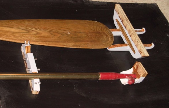
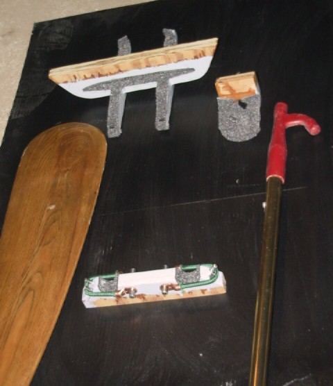
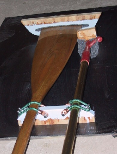
During previous usage of the boat, the paddle and boat hook were just stowed loosely behind one of the side trim panels and were retrieved when needed. In this location they moved around and were subject to damage during rough water activity. The underside of the foredeck had adequate length to stow them so a bracket system was devised to be incorporated into the underdeck structure. The brackets were made from wood and will be bonded into place to the cross strips. The second layer of foam will have cutouts to accommodate the brackets.

The paddle and hook brackets prior to adding the carpet padding. The brackets on the right will be mounted forward and the left will be mounted near the instrument panel. The left bracket is also shown inverted relative to the other two, for clarity. The lead-in to the forward brackets will provide easier location for sliding the paddle and hook into place.

The brackets are designed to make it easy to retrieve and replace the paddle and hook in their respective positions under the deck. The front brackets have lead-in surfaces to guide the items into their holes and the rear bracket has bungee cords to hold the handles up into place. Not shown but to be incorporated are stops that will keep the parts from sliding rearward during boat operation.

The brackets with the carpet padding installed. Note also the bungee cords on the lower bracket to hold the handles of the paddle and hook. Again, the bottom bracket is inverted relative to the other two for clarity.

The bungee cords were made by cutting the length desired and then epoxying the ends into electrical terminals. The pins for securing the bungee cords are stainless steel and were bonded into their mounting holes with epoxy.

The paddle and hook installed in the brackets as they will be mounted. The lower bracket is shown closer to the upper brackets for picture purposes. In the installation it will be near the handle ends of the paddle and hook.

In a later post showing the under deck reinforcement build, a picture will be included which shows the brackets as they are installed.
Attachments:

Please Log in or Create an account to join the conversation.

Re:1963 Glastron V143 JetFlite Restoration 10 years 10 months ago #89200

  • Kern
  • Offline
  • Junior Boarder
  • Junior Boarder
  • Posts: 105
  • Karma: 17
  • Thank you received: 1
The foredeck was made of relatively thin fiberglass and tended to flex when crawling on it to board, paddle, or retrieve the anchor. This flexing produced spider cracking in the gel coat. The plan was to create a more solid and stable foredeck so the new finish would not crack from flexing.

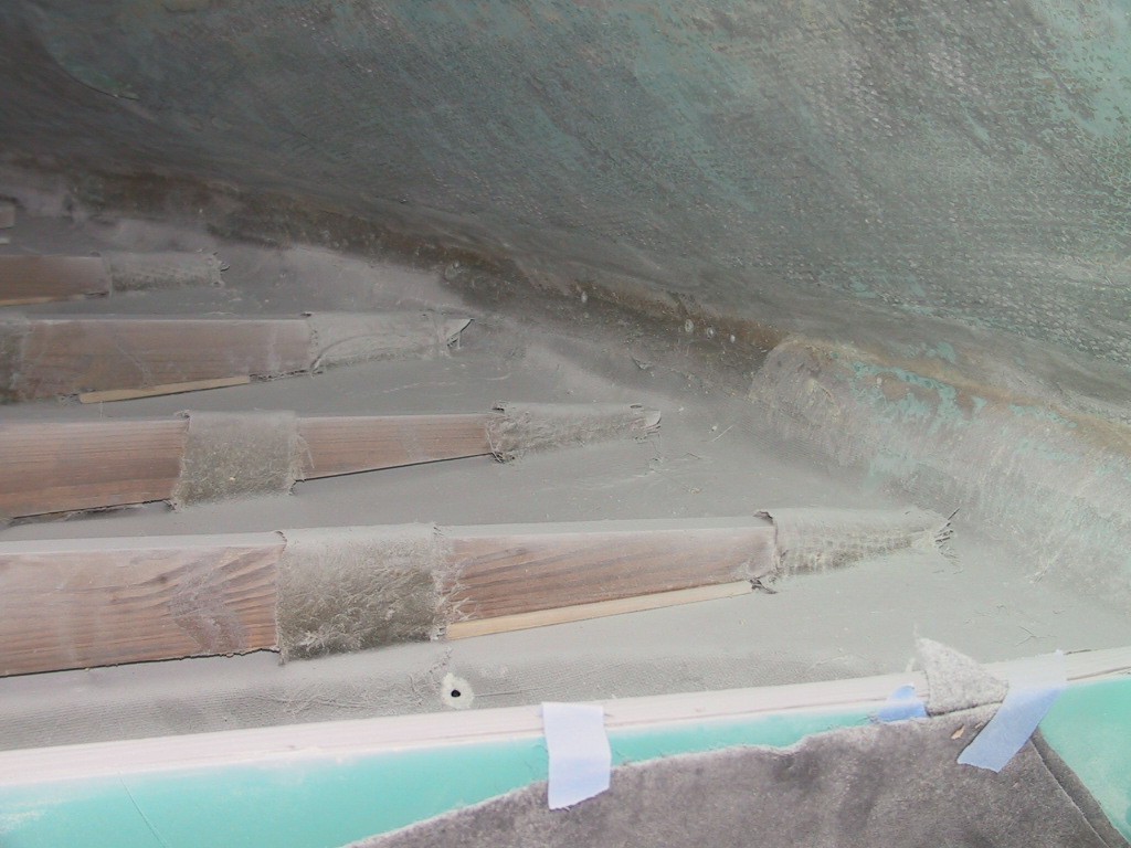
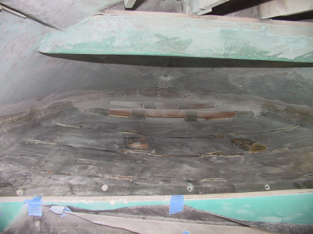
The factory support for the foredeck consisted of five wood cross braces that were tabbed to the underside of the foredeck. These were shaped approximately like the underside of the deck but were not fitted precisely. To fill any gaps, the factory used corrugated cardboard as shim strips. Starboard Marine attempted to improve this situation by making wood shims to give better support. There was still no support for the deck between the cross braces.

The original cross braces, tabbed in place.

Cleaning up the underside of the foredeck by grinding away all the old materials.

As originally delivered, the boat had flotation foam planks tied to the foredeck cross braces. I loaned the boat to my brother for a couple of seasons and when it was returned, these planks were missing. I assume they gave him some trouble at some time so he just removed and discarded them.

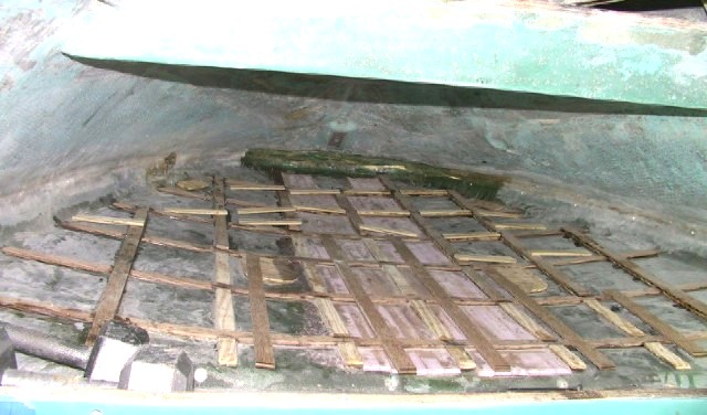
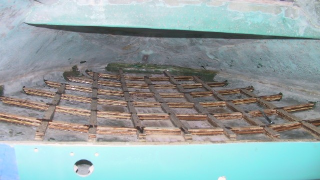
The new goal for the foredeck is to create a support system that will provide a solid, non-flexing deck surface, along with adding flotation to the front of the boat. A design was created using one inch wide strips of ¼ inch plywood to provide deck support. These will be laid on a 7 by 9 inch grid so the rectangles between the strips will be 6 by 8 inches. The one inch strips provide more support area than the ¾ inch original cross braces, even including their tabbing. The grid also adds support area by providing six cross supports and seven longitudinal supports.

The layout of the grid.

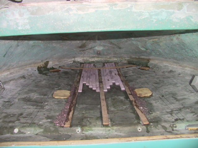
The center of the deck has a section that is 15 inches wide and is raised about ¼ inch above the main deck. The underside of this raised area will be fitted with three longitudinal wood strips with foam between them. The foam is not available in ¼ thickness so strips ¼ thick were cut from the one inch sheets. These were then laid side by side to fill between the longitudinal wood strips.

Partial completion of the center section with the first cross strip bonded in place.

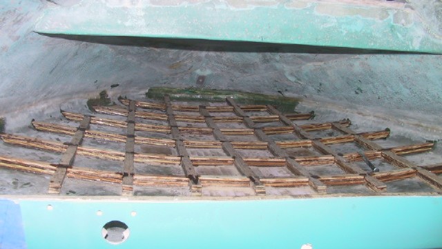
The grid will be bonded to the underside of the deck for good conformity and support and built up to four layers of plywood for a one inch height. At the grid intersections, the through strip will alternate with one layer having the cross strips going through the intersection and the longitudinal strips being interrupted. The next layer will have the longitudinal strips running through and the cross strips interrupted. All strips were bonded in place, one layer at a time.

The planned grid for the deck support is made up of many pieces cut, laid, and bonded in place one at a time. The total listing of the pieces is:
Plywood strips
17 Longitudinal - varying lengths
62 Longitudinal - 8 inch
12 Cross - varying lengths
64 Cross - 6 inch
28 Short - varying lengths
Foam
12 Strips - ¼ X 1 - varying lengths
24 Blocks - one inch thick - 6 X 8 inches
20 Blocks - one inch thick - varying sizes and shapes

Building the second layer of strips. The cross pieces laying at angles are waiting to be installed.

The completed wood grid.

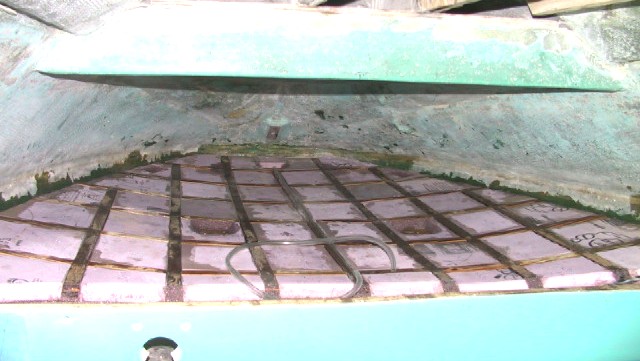
After the grid was completed, the first layer of foam blocks was inserted into the grid voids and bonded into place. Access holes were left in the foam for deck hardware installation and notches were cut around the edges for rub rail hardware installation. A length of clear tubing was bonded to the center strip to use as a conduit for routing the wires to the bow light.

The first layer of foam blocks bonded in place within the grid. The clear tube for the bow light wiring is visible along the center strip.

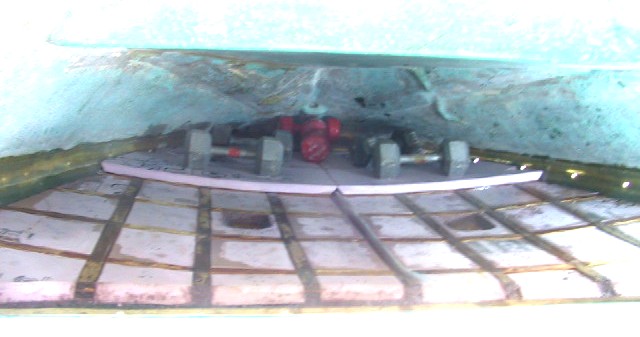
After the first layer was complete, panels were cut and fitted for the second layer. To ease fitting and bonding into place, this layer was made using nine inch wide panels whose edges were centered on the cross strips. The panels were weighted to get conformity to the curvature of the deck during curing of the resin. As in the first layer, access was provided for deck and rub rail hardware.

Starting the second layer of foam.

The completed second layer with the paddle and boat hook brackets in place.

The paddle and boat hook stowed in their brackets. This picture was taken with the boat upside down and has been inverted to show how the installation will look with the boat right side up.

There is still some minor cleanup and reshaping of the foam to do, then it will be coated with epoxy for durability, and painted.

The estimated flotation from the installation is 180 pounds. I have not tested the deck stiffness yet but believe that it will be quite adequate.

The support of the foredeck may have been adequate with just the two layers of foam but I did not want to take the chance of installing just the foam and then finding that it was not adequate.

Please Log in or Create an account to join the conversation.

Re:1963 Glastron V143 JetFlite Restoration 10 years 9 months ago #90693

  • Kern
  • Offline
  • Junior Boarder
  • Junior Boarder
  • Posts: 105
  • Karma: 17
  • Thank you received: 1
CENTER CONSOLE REBUILD

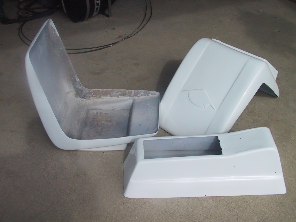
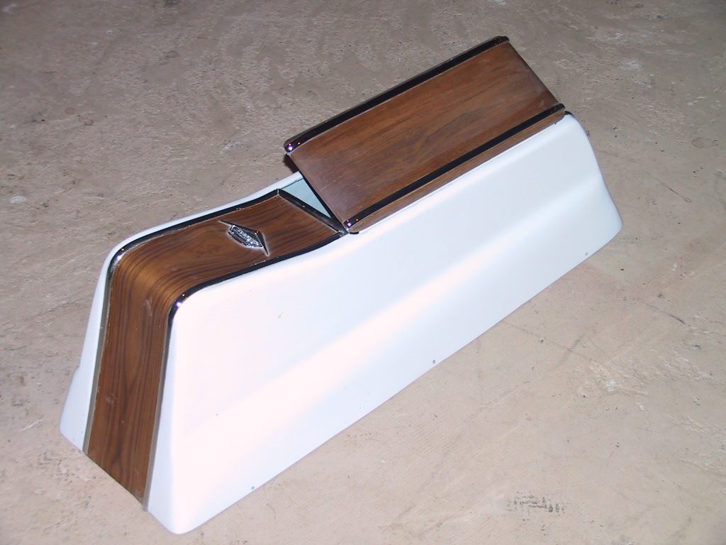
As originally built, the center console had a front hinged lid which was covered in white vinyl with an embossed pattern, edged with a vinyl strip, had an exposed hinge with exposed rivets, had a gold mylar trim on the front and rear centers, and had a pebble grain pattern molded into the outer surface. The overall effect was functional but not very upscale in looks.

The original center console. The motor controller was added when the motor was mated to the hull.

With the Polar Vortex keeping things cold and snowy here, work on the hull has been minimal. Meanwhile, other small projects that can be completed indoors are being tackled. After completion of the seats, the console was next.

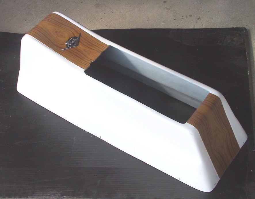
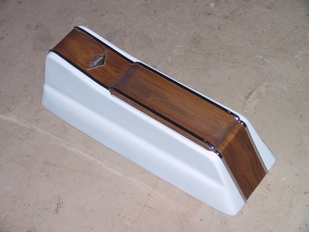
As finished by City Auto Body, the console surface was filled smooth and painted a glossy white.

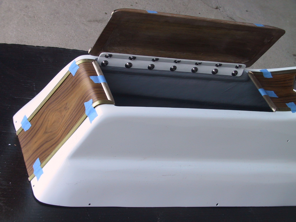
Dick at Starboard Restorations suggested a wooden lid and it was decided to use a wood veneer to replace the gold mylar trim that was original to the console. A visit to a hardwood shop resulted in choosing a teak veneer and a teak board for the lid.

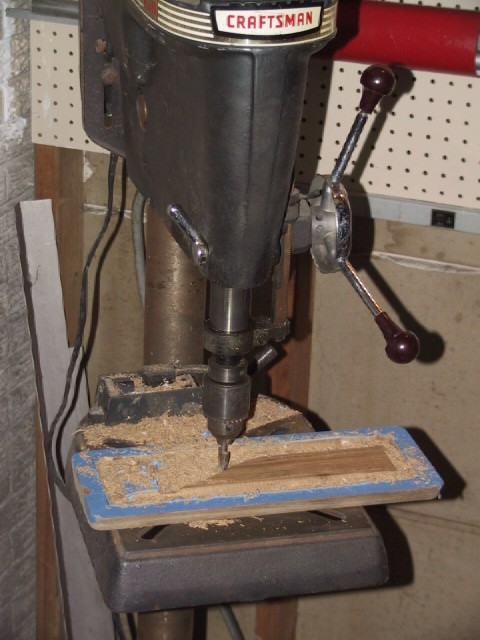
The underside of the lid was relieved to provide a little more room in the console. A router bit in the drill press was used to cut the relief as this allowed a better view of the cutting process.

[/i] A wood strip was bonded into the upper port corner of the console to provide an attachment surface for the new lid hinge.

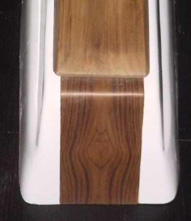
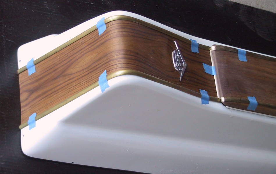
The veneer was bonded to the front and rear center areas of the console using contact cement. The radius at the top rear was small and resulted in cracking of the veneer when it was bent over the radius. A new piece was cut and submerged in water until it was saturated. It was then bent and bonded with no cracking.

When making the veneer, the manufacturer used book matching at the joints between strips. This resulted in some interesting patterns in the graining. If you look closely at the pictures, there are two fox faces on the console – one forward of the Glastron emblem and one on the rear surface.

The veneer was finished with several coats of clear polyurethane, sanded smooth, and rubbed with steel wool. This produces a very smooth satiny finish that is easily repaired if necessary.

The veneer glued to the console and finished with polyurethane.

After shaping, the lid was finished in the same way as the veneer. Since it was a different piece of wood, the final color was lighter than the veneer so it had to be stripped, stained, and refinished with urethane. If I had tried a test piece prior to finishing the final part, I could have saved considerable time and materials.

The first finish on the lid was lighter than the veneer.

The new hinge on the port side of the console.

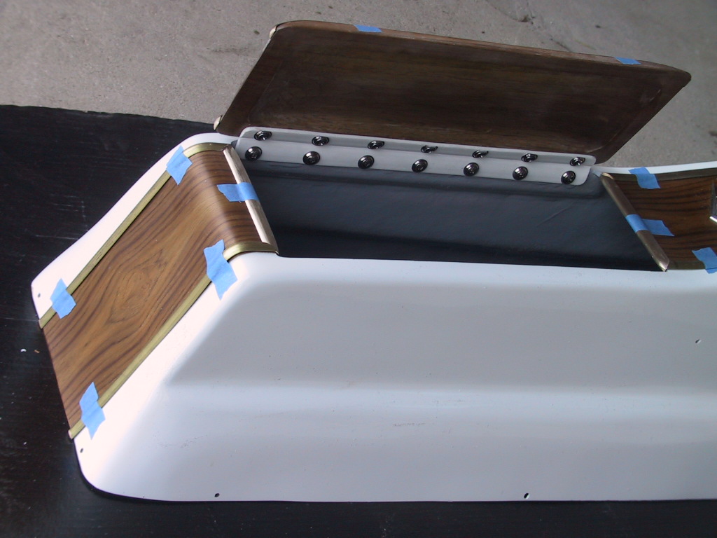
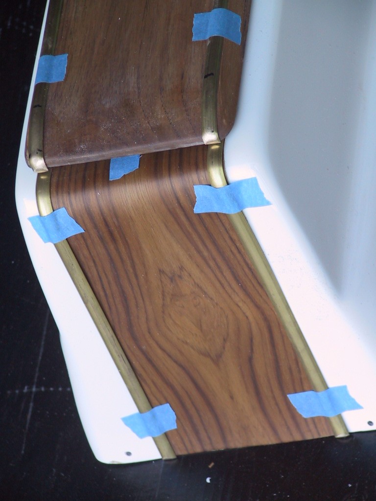
As a finishing touch, the edges of the veneer will be trimmed with chrome trim strips. This will be consistent with the edge strips used on the foredeck and side decks to trim the vinyl inserts. Similar trim strips will be used on the instrument panel edges. The strips are brass for ease of forming and will be chrome plated prior to installation. The strips were hand formed and finish shaped. The pictures show the strips on the console for a test fitting prior to being sent out for polishing and chroming.

The trim strips on the front of the console.

The rear trim strips.

With the lid open, the trim strips at the front and rear of the console opening can be seen.

The instrument panel will be receiving a veneer finish surface with similar trim strips along the exposed edges.

Please Log in or Create an account to join the conversation.

Re:1963 Glastron V143 JetFlite Restoration 10 years 9 months ago #90715

Excellent, it looks awesome!!!!!!!!!!!

Bob

Please Log in or Create an account to join the conversation.

Re:1963 Glastron V143 JetFlite Restoration 10 years 9 months ago #90732

  • MarkS
  • MarkS's Avatar
  • Offline
  • Moderator
  • Moderator
  • Posts: 5348
  • Karma: 118
  • Thank you received: 5
Outstanding attention to detail Kern, top shelf work IMHO!

Please Log in or Create an account to join the conversation.

Mark

Re:1963 Glastron V143 JetFlite Restoration 10 years 9 months ago #90873

  • Kern
  • Offline
  • Junior Boarder
  • Junior Boarder
  • Posts: 105
  • Karma: 17
  • Thank you received: 1
Thank you, gentlemen, for your complimentary words. I am somewhat frustrated that many of these processes, including designing and making new parts, take so long. I would like to see it move along faster. Your words help to keep the motivation going.

I hope that showing these processes will help other builder/restorers in seeing potential in their projects and help show them how to accomplish some of their build/update/restoration.

Lots more to come.

Please Log in or Create an account to join the conversation.

Re:1963 Glastron V143 JetFlite Restoration 10 years 8 months ago #91806

  • Kern
  • Offline
  • Junior Boarder
  • Junior Boarder
  • Posts: 105
  • Karma: 17
  • Thank you received: 1
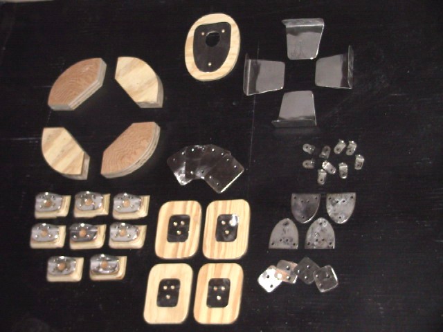
The cold is preventing hull work so various items are being fabricated indoors in preparation for later assembly. When doing a rebuild/upgrade such as this, it is necessary to create new components to accommodate the new design. Also, in some cases, existing components are replaced with improved versions.

The accompanying picture shows some of the new items that will be incorporated into the boat. All metal parts are made from stainless steel. The thinner plywood parts are deck reinforcements that are installed under the deck to spread any loads from stressed deck hardware, such as cleats, chocks, hinges, and the stern light. The backing plates that are used with these reinforcements help to spread the loads over a larger portion of the reinforcement and result in less compression of the wood than would be the case with typical flat washers. The corners of the reinforcements and backing plates are rounded to create less concentrated stress than would be the case with square corners.

The deck reinforcements for the cleats and chocks are not shown as they are already bonded into the hull.

The angle brackets that will be screwed to the floor and used to tie down the battery and fuel tank have wood risers that will be installed under them. These risers will be bonded to the floor and will provide additional thickness so longer screws can be used to attach the brackets.

The wooden risers for the fuel tank will be bonded to the floor and will raise the tank off the floor to provide ventilation under the tank to prevent any moisture accumulation.

There will be other special parts that will be needed and they will be designed and made with similar materials and processes.

Items shown are: in the center are back-up plates for the cleats, and starting at 12 o'clock and going clockwise - the stern light deck reinforcement and back-up plate - interior side panel to bottom brackets - console mounting brackets - mounting plates for the tonneau cover latches - tonneau cover hinge back-up plates (cover hinge half) - tonneau cover hinge deck reinforcement and back-up plate (hull hinge half) - risers and hold down brackets for the battery and fuel tank - fuel tank riser blocks.
Attachments:

Please Log in or Create an account to join the conversation.

Re:1963 Glastron V143 JetFlite Restoration 10 years 8 months ago #91829

Most excellent.

Bob

Please Log in or Create an account to join the conversation.

Re:1963 Glastron V143 JetFlite Restoration 10 years 8 months ago #93179

  • Kern
  • Offline
  • Junior Boarder
  • Junior Boarder
  • Posts: 105
  • Karma: 17
  • Thank you received: 1
During the transom rebuild the rotisserie proved its worth. The hull could be rotated to whatever angle was most beneficial for doing whatever work was currently needed. When applying resin to the parts, the hull could be placed at the angle that allowed the resin to flow by gravity down into any cavities between parts that needed filling.

As previously discussed, all the old, rotted sections of the original transom structure were cut out. The bottom cross board below the new center section was also weak with some rot so it was cut out and a replacement board was fitted.

Cutting out the weak bottom board of the transom. The boat is upside down in this picture. The aluminum angle can be seen in this picture. The bottom leg is against the bottom of the motor well and has holes in it. The end of the upper leg can be seen protruding out from the side of the motor well in front of the new center transom board.

Then an analysis was made to determine the best way to rebuild the transom structure to insure that it will be strong and long lasting. The transom of this boat is 17 inches high. The forces of propulsion create a torque effect on the transom where the motor mount attaches. This torque is pushing forward at the bottom of the motor mount (10 inches from the top) and pulling aft at the upper screw clamps (2 ½ inches from the top). So most of the forces on the transom are on the upper half. The previously installed aluminum angle transfers some of these torque forces into the bottom of the motor well, increasing the area to resist the forces.

The original transom board had its widest section at the bottom where the transom meets the floor. It then tapered up to the corners where the top of the motor well meets the transom on each side. This design does not optimize the spread of maximum forces into the sides of the transom for more load carrying area.

The new design will have the widest portion of the transom board at the top with the width tapering down toward the bottom below the outer sides of the motor well. The original center section as installed by Starboard Marine will be left in place.

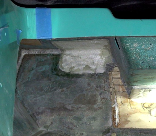
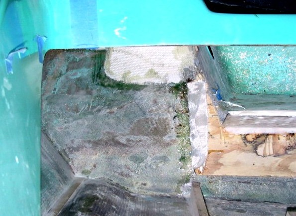
Prior to installing the new transom side boards, a layer of heavy fiberglass cloth was bonded into place reinforcing the upper transom to rear deck area from the motor well outboard about 10 inches. This will transfer any upper transom forces into the rear upper deck, further spreading the loads.

The fiberglass cloth bonded to the transom and upper deck joint.

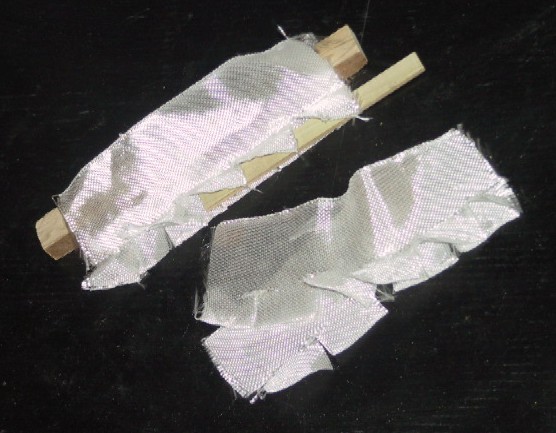
Because the transom board will now be three pieces, a very stiff joint will be required between the center and outer boards to minimize flex and maximize force transfer. This will be accomplished by adding two structural elements into the design. The first will be two layers of interwoven fiberglass cloth that will be fitted into the joint between the center and side boards. The cloth will be inserted as two “S” section pieces running for as much length of the joint as possible. The “S” sections will be formed by having the transom skin end of one piece behind the center board, routed through the joint between the boards, and attach to the front of the side board. The other piece of fiberglass will have its transom skin end behind the side board, pass through the joint, and bond to the front of the center board.

The two layers of glass cloth interwoven to form a double "S" pattern to strengthen the joint between the center and side boards.

The double layer of glass cloth attached to the center board with one layer in front and one behind, ready for the side board.

One of the new side boards bonded into place. Note the glass cloth of the joint, one layer on the front of the center board and the other layer on the front of the side board.

The other load spreading part of the design consists of ¼ inch stainless steel rods that are inserted into horizontal holes drilled between the aluminum angle and the center transom board. These rods will extend outboard onto the new side board sections and will be bonded to both center and side boards. Rearward loads on the upper transom will be transferred into the aluminum angle, then to the stainless rods, outward to the side boards, into the outer transom and rear deck areas.

The stainless steel load distribution rods in place. The inner ends are between the new center transom board and the aluminum angle and the outer ends bear onto the new side boards.

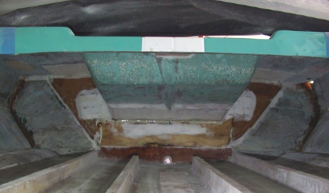
The completed transom structure. The stainless steel rods have been encased in epoxy and all wood parts are coated in epoxy.

The rearward forces on the upper transom will now be distributed to the bottom of the motor well, to the upper outer transom and to the upper deck alongside the motor well side wall. With this redesign, the transom should resist water penetration, be quite strong, and easily capable of handling motor horsepower ratings of over 100 horsepower. However, the original 65 horsepower motor will be kept with the boat as long as I own it.

Please Log in or Create an account to join the conversation.

Re:1963 Glastron V143 JetFlite Restoration 10 years 6 months ago #96333

  • Kern
  • Offline
  • Junior Boarder
  • Junior Boarder
  • Posts: 105
  • Karma: 17
  • Thank you received: 1
As someone once said “Things are a-changin”. My wife and I have decided to move to a new, warmer, location. I have always wanted to live near water and the restoration of the Glastron has added an incentive to do so. We have found a home overlooking Table Rock Lake in southern Missouri and will be moving in a few months.

What this means to the boat project is that I have to get certain portions of the rebuild completed prior to moving the boat. That has resulted in reordering the priorities regarding what portions are getting attention.

One area that has moved forward is to get the interior boards shaped and fitted so they can be sent to the upholstery shop. Other areas of priority are to complete the transom motor mount area so the motor can be mounted for transport and getting the tonneau covers fitted with hardware so they can be in place during the trip.

Prior to fitting the interior side boards, the inside vertical surfaces had to be stabilized in position. The factory attachment at the bottom was by screwing the fiberglass to a wood block that was crudely bonded into the hull near the chine. These were removed and stainless steel angle brackets were formed as a lower mount.

The original wood blocks that anchored the inside deck extensions for interior trim mounting.

The angle brackets were bonded and glassed in place to the inside bottom near the chine, creating a much cleaner, more finished, look, that is more open for access. This area will not be visible but I will know how it was assembled.

The chine area had longitudinal wood strips bonded in place with resin. These were ground out and the inside chine profile was a lazy V lying to one side. New strips were bonded into place and the chine cavity was filled with resin up to the level of the inside bottom surface inboard of the chine edge. This provides good chine strength and would permit a significant chine impact without creating a hole in the hull. I do not plan to test this theory.

Bonding the wood strips into the chine cavity.

The interior light shown in the last picture is in place to check the position prior to cutting the holes in the wood side panels. This light was not original to the boat. It is a Hella unit that was used in various cars, including the Jaguar XJ-S. It was chosen for its shape and the chrome trim, which is typical of the era of the boat. Another neat feature of the light is the switching. The internal switching is accomplished by tipping the lens. Center position is off, tipping one way turns the light on, tipping the other way connects the light to a remote switch that can activate the light. The final installation of the electrical system will have a four switch bank on the instrument panel, one of which will be for interior lights. There will be the two lights in the rear compartment and two under the instrument panel.

The final assembly with the stainless steel angle bracket anchoring the deck extension to the floor and the chine cavities completely filled with resin with a smooth top surface.
Attachments:

Please Log in or Create an account to join the conversation.

Re:1963 Glastron V143 JetFlite Restoration 10 years 6 months ago #96567

  • Kern
  • Offline
  • Junior Boarder
  • Junior Boarder
  • Posts: 105
  • Karma: 17
  • Thank you received: 1
With the planned underfloor foam that will be completely filling the cavity between the floor and bottom, I had decided to decrease the floor thickness to 3/8 inch to save a slight amount of weight. With the floor this thin there was some concern over the grip of screws that would be driven into the floor.

Anchor nuts were created to attach to the floor and accept the mounting screws for the seats. Other screws would be necessary to attach various other bits and pieces to the floor and decking. Another concern with penetrating the wood with screws was that this would be a potential point where water could seep into the wood and create weakness or rot.

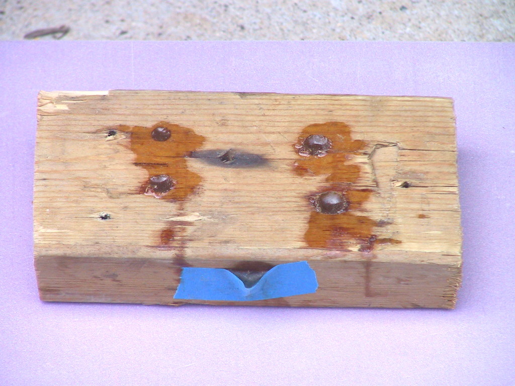
To seek a possible solution to this issue, I decided to try an experiment with an alternate method of fastening. The plan was to drill a hole in the structure (wood, wood over foam, fiberglass) that would be larger than the desired fastener, then fill that hole with resin and allow it to harden into a plug. Then that plug would be drilled and tapped for a stainless steel machine screw with the desired thread size.

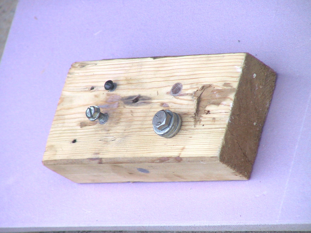
I used a scrap piece of 2 X 4 as my test block. The drilled holes were approximately 1/8 larger than the outer diameter of the thread. I used a ¼ drill for the # 10 screw, a 3/8 drill for the ¼ screw, a 7/16 drill for the 5/16 screw, and a ½ drill for the 3/8 screw. In addition, I drilled a hole in the side of the block to test a plan to be able to create horizontal plugs where it was not possible to rotate the hull to get the hole to a vertical position.

The first picture shows the block with the holes filled with resin. The horizontal hole was successfully filled by placing the blue tape to form a side funnel arrangement.

The resin plugs fill the drilled holes.

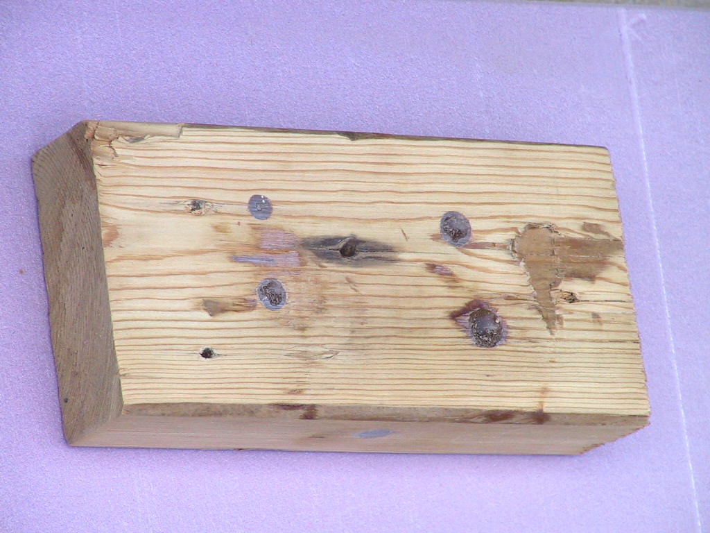
The surfaces after sanding, preparing for the drilling and tapping.

The final picture shows the block with holes tapped and screws inserted. I learned that it is best to remove the tap part way in to clean the grooves of debris. If I left the debris in place the deeper threads are not cut cleanly and are less strong. With this process, the usual depth rules probably need to be exceeded as this is not a metal base. The deeper the tapped hole and the longer the fastener, the stronger will be the result. Just do not drill a hole in the bottom. :lol:

Test screws in place to check the strength of the plugs and threads.

To test the strength of the final result, washers, with holes larger than the plugs, were placed under the screws and the screw was tightened to see if the plug would pull out or strip its threads. I did not use a torque wrench but tightened the screws to a level that was quite adequate for the size. The plugs stayed in the block and the threads held the load.

Obviously, this procedure is more time and labor intensive than just driving a wood screw. On my restoration I am seeking the best solutions I can create for the final result. Cost and time are not considerations. For many others, they are considerations so this method may not be appropriate for your use. If you like it, feel free to use it. That is the reason I am sharing.
Attachments:

Please Log in or Create an account to join the conversation.

Re:1963 Glastron V143 JetFlite Restoration 10 years 6 months ago #96816

  • Kern
  • Offline
  • Junior Boarder
  • Junior Boarder
  • Posts: 105
  • Karma: 17
  • Thank you received: 1
Many of the changes and upgrades being made to the boat will be adding weight to the hull. To compensate somewhat for this added weight, ways to remove weight are being sought. Decreasing the floor thickness will decrease the floor weight by about 6 pounds.

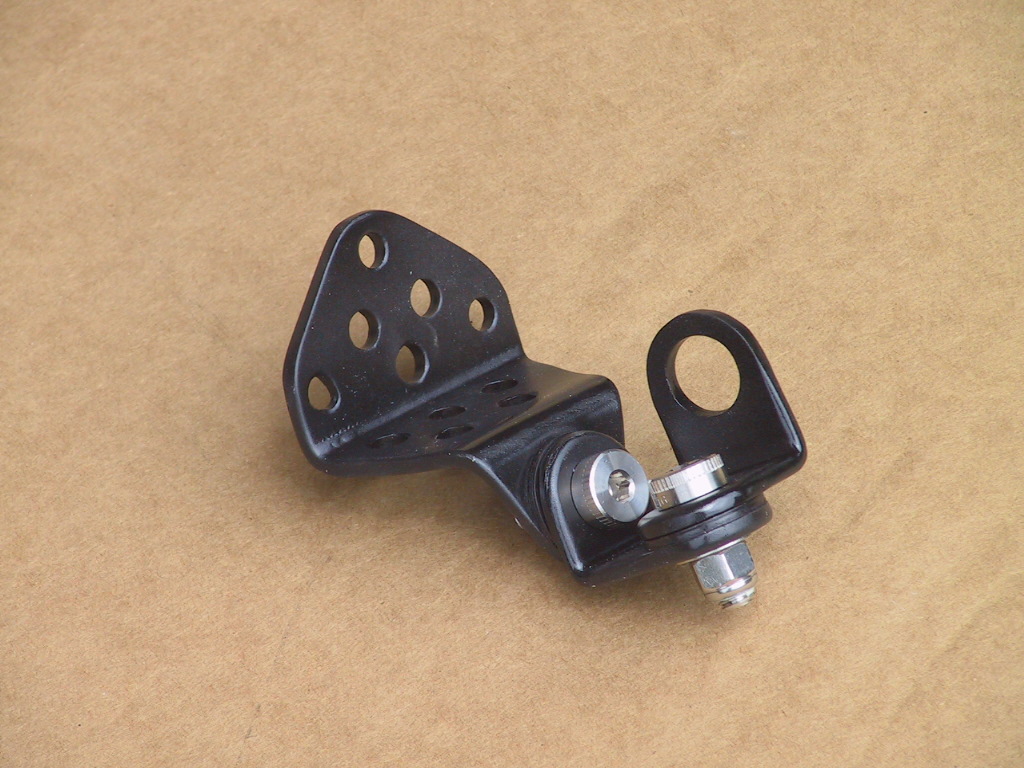
The steering cable assembly was surprisingly heavy. The rear mount needed refinishing so weight was removed while refinishing. The assembly was also improved by changing the method by which the pieces were attached together.

The two pictures following show the mount before and after modification and refinishing. The original assembly was held together by two large rivets. A thin plastic washer was between the parts at each pivot point. One of the rivets was not set tight so the joint movement was sloppy.

The original transom mount for the steering cable.

The lightened mount with improved assembly quality.

The revised assembly uses stainless steel hardware for assembly. Shoulder bolts were used in place of the rivets and thicker nylon washers were used between the moving parts. The nuts were tightened onto the shoulders of the bolts, resulting in a tight, no-slop assembly that will not be affected by vibration.

The original assembly weighed 600 grams and the new assembly weighs 470 grams for a saving of about 1/3 pound. A lot of work for a small gain. Rational - NO. Interesting challenge and fun - YES. When combined, the small gains can reach meaningful levels.

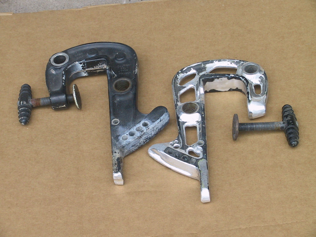
The motor is another area that will be explored for weight savings. Much of the assembly is aluminum and it is harder to make significant weight gains. The following photo shows the motor clamps before and after lightening. In this case the weight loss was about ½ pound. Again, a lot of work for a small gain.

The original and lightened motor clamp legs.

The motor has not been reviewed to see where weight reductions are possible as that is planned for the future, after the hull is completed. It is hoped to be able to remove between 20 and 30 pounds total from the motor. Will keep you posted.

A significant amount of weight will be saved in the use of new battery technology. Originally the boat carried a typical lead-acid battery that weighed about 40 pounds. The new plan is to use a Lithium-iron battery that weighs about 2 ½ pounds. This weight savings will be near the stern and should help with getting the boat on plane more quickly.
Attachments:

Please Log in or Create an account to join the conversation.

Re:1963 Glastron V143 JetFlite Restoration 10 years 3 months ago #100571

  • Kern
  • Offline
  • Junior Boarder
  • Junior Boarder
  • Posts: 105
  • Karma: 17
  • Thank you received: 1
Work is progressing slowly on many areas, getting ready for our impending move to Missouri (Probably next spring). The trailer was not ready for the road so some items are being completed toward that end.

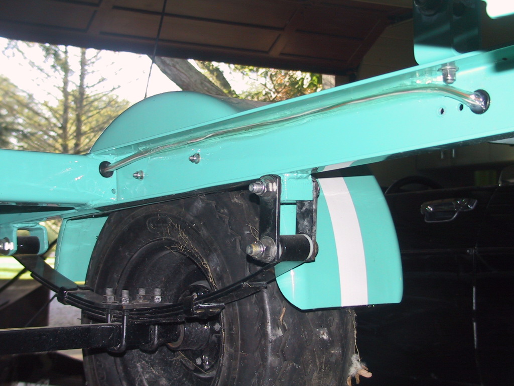
In previous postings about the trailer, I did not mention that one of the other major modifications was to move the axle rearward six inches. This moves some weight to the tongue for better balance and more stable towing. Another upgrade was to change all the bolts, nuts, and washers to stainless steel with the nuts being self locking with nylon inserts.

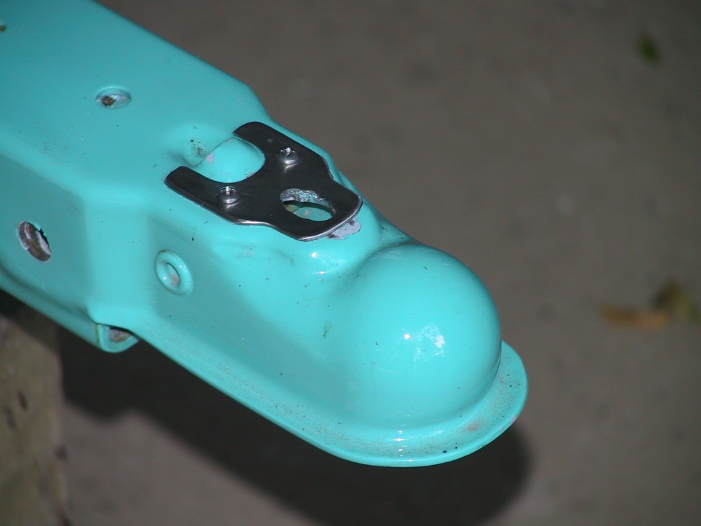
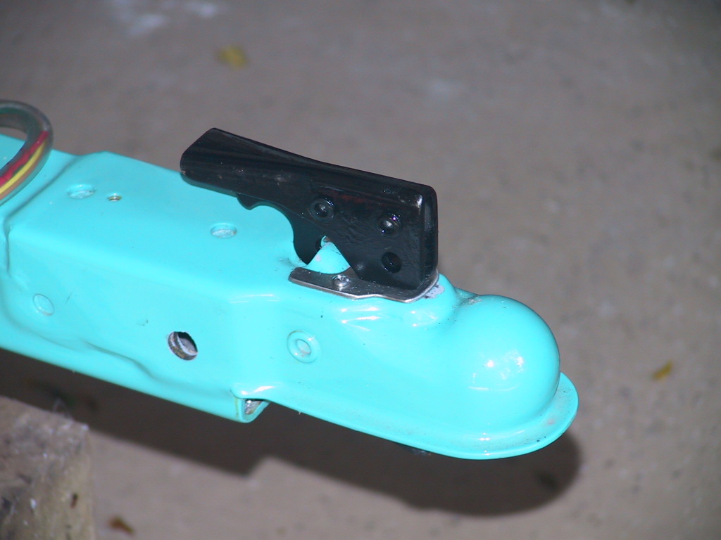
Even though the trailer has not been used since painting, the hitch latch has already marred the paint where it bears on the top of the hitch.

The damaged area will look bad and be subject to surface rust.

A stainless steel wear plate was made to take the sliding of the latch when it is moved during trailer hookup. The visible paint damage ahead of the wear plate will be touched up with paint when doing other paint detail work.

The wear plate in position. It was sealed under the plate with silicone.

The addition of the wear plate changed the geometry of the latch mechanism so the dimensions had to be modified to provide a secure latch with proper operation.

The latch mechanism resting on the plate. No rust!
Attachments:

Please Log in or Create an account to join the conversation.

Re:1963 Glastron V143 JetFlite Restoration 10 years 3 months ago #100627

Very nice job on the finishing. Its a very cool little boat, and your trailer is pretty slick

But I have to say the pictures of the transom make me cringe :unsure:

The stainless pieces will initially take 100% of any loads (glass stretches/elongates) then the resin will pull away from the stainless (it does not bond well to stainless), so then you have the glass taking 100% and the stainless pieces just in there doing nothing other than starting to corrode (stainless will oxidize if encapsulated)

The person who initially did the transom job should never have taken the job if could not do it right. He just put in a some plywood and covered it with a little mat.

guaranteed way to rebuild better than original: Remove original core, epoxy in new core, glass in new core (epoxy and biaxial glass), new inside skin must overlap the sides and bottom, then you add any knees or transom extensions you might require.

I hate to be a downer, but there is just a much better way to do this. The short cuts end up costing more time and $$$ If you remove the cap you can quickly layer in some foam core (real foam core, not EPS that will delaminate) into the forward deck, then glass over it. With cap off you then have very good access to replace transom, stringers, sole.

Again, Im sorry my first post is critical, but I do really like all the finishing work your doing ;)

Please Log in or Create an account to join the conversation.

Re:1963 Glastron V143 JetFlite Restoration 10 years 3 months ago #100633

shine,

WELCOME ABOARD.

yours, satx

Please Log in or Create an account to join the conversation.

Resistance to tyrants is obedience to Almighty God.
Thomas Jefferson, 1803

Re:1963 Glastron V143 JetFlite Restoration 10 years 3 months ago #100653

  • Kern
  • Offline
  • Junior Boarder
  • Junior Boarder
  • Posts: 105
  • Karma: 17
  • Thank you received: 1
Shine,

Welcome aboard and thank you for your input regarding my project and thank you for the compliments regarding the work being done. Critical posts are sometimes necessary and useful to help others. They, though, have to be willing to accept the information in the post and take it under advisement.

I agree that the initial person should not have taken the project if he could not do it properly. I found his shop on the internet and pictures of projects completed led me to feel that he would be able to complete the project better than a typical boat dealer/repair shop. Most of his previous work was with wood boats but he had completed several fiberglass boats and claimed to have a very good fiberglass man to do the job.

In later dealings I learned that he was short on work and needed to get some activity to help cash flow, so perhaps jumped into the project just to get work. I also learned that his standards were somewhat short of my expectations. This is why I caution anyone embarking on a project like this to carefully interview the builder and make certain that everyone is in agreement regarding the level of build quality to be achieved.

I was not aware that encapsulated stainless steel will oxidize. It would seem to me that to create oxidation, one would need air and/or water to reach the parts. I have tried to make this design/construction to allow neither. The load paths from the motor mounts to the transom are such that the stainless rods have primarily compression in the fore/aft direction so the forces to pull resin away from the rods should be lower than forces of resin pushing on the rods. The previously installed aluminum angle also spreads loads over a large area on the bottom of the motor well. I am expecting the combined structure to be quite stable. I also have another idea that I want to try when I get the boat functioning. This new idea will change the positioning and distribution of transom loads.

As mentioned in the write-up, all of this major rebuild should have been done before the boat was painted. However, the need for the redesign was not found until after paint so various decisions have been made to minimize the tear-up and damage to the new paint.

Had I known what was down the path on the restoration, I would not have taken the boat to someone else and would have rebuilt the transom myself. It would probably have been less work and the outcome would have been more like your suggestions.

Again, thank you for your input.

Please Log in or Create an account to join the conversation.

Re:1963 Glastron V143 JetFlite Restoration 10 years 2 months ago #101020

  • Kern
  • Offline
  • Junior Boarder
  • Junior Boarder
  • Posts: 105
  • Karma: 17
  • Thank you received: 1
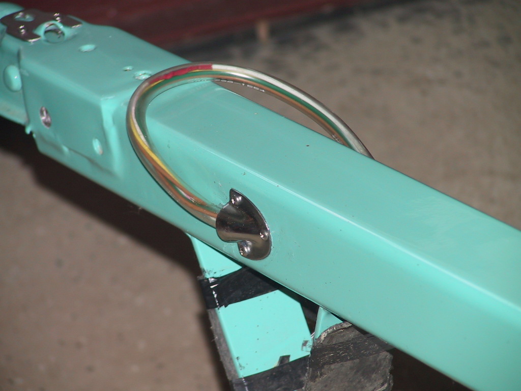
The next trailer project was to build a wire harness and connect the taillamps to the vehicle plug. Some may wonder about why I am placing so much emphasis on the trailer build in this narrative. It is my belief that the boat and trailer are a complete entity as the boat is seen on the trailer more than it is by itself on the water. I therefore feel that the trailer should compliment the boat and vice versa in the build quality and appearance.

The harness enters the tongue rail on the side through a PERKO scoop. The opening is sealed with silicone.

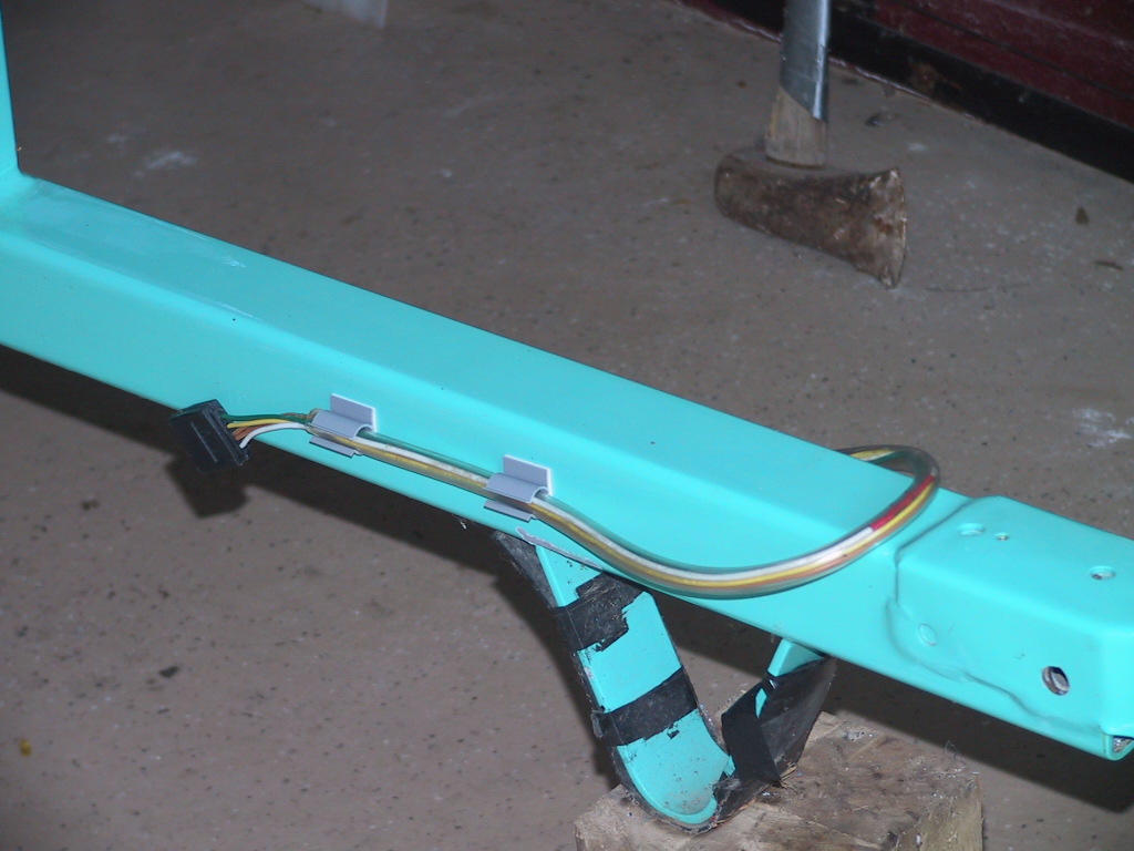
When not connected to a vehicle the harness is stowed in plastic clips on the side of the tongue.

The plan was to minimize the need to drill holes in the frame rails for retaining clips. To achieve that goal, the decision was made to route all the wiring inside clear, flexible, pvc tubing and bond the tubing to the frame rails using silicone.

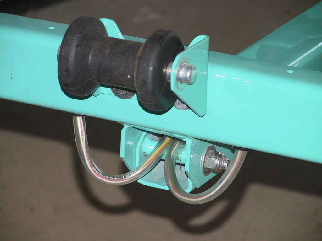
The trailer is a tilt bed with a pivot at the rear end of the tongue rail. Over time this pivot cannot be relied upon to always provide a good ground through the trailer frame, so a separate ground wire was routed from the vehicle plug back along each side to its respective taillamp. All wires were first pulled through the tubing that ran through the tongue rail. At the back of the tongue rail, the two sides were separated and run through separate tubing to the lamp on that side. At the rear of the tongue rail the two side harnesses were joined to the tongue harness using silicone seal and heat shrink tubing to obtain a water tight junction.

At the rear of the tongue rail a junction was created to split the harness to each lamp.

The junction was pulled forward into the tongue rail and each side harness was routed to its side of the trailer.

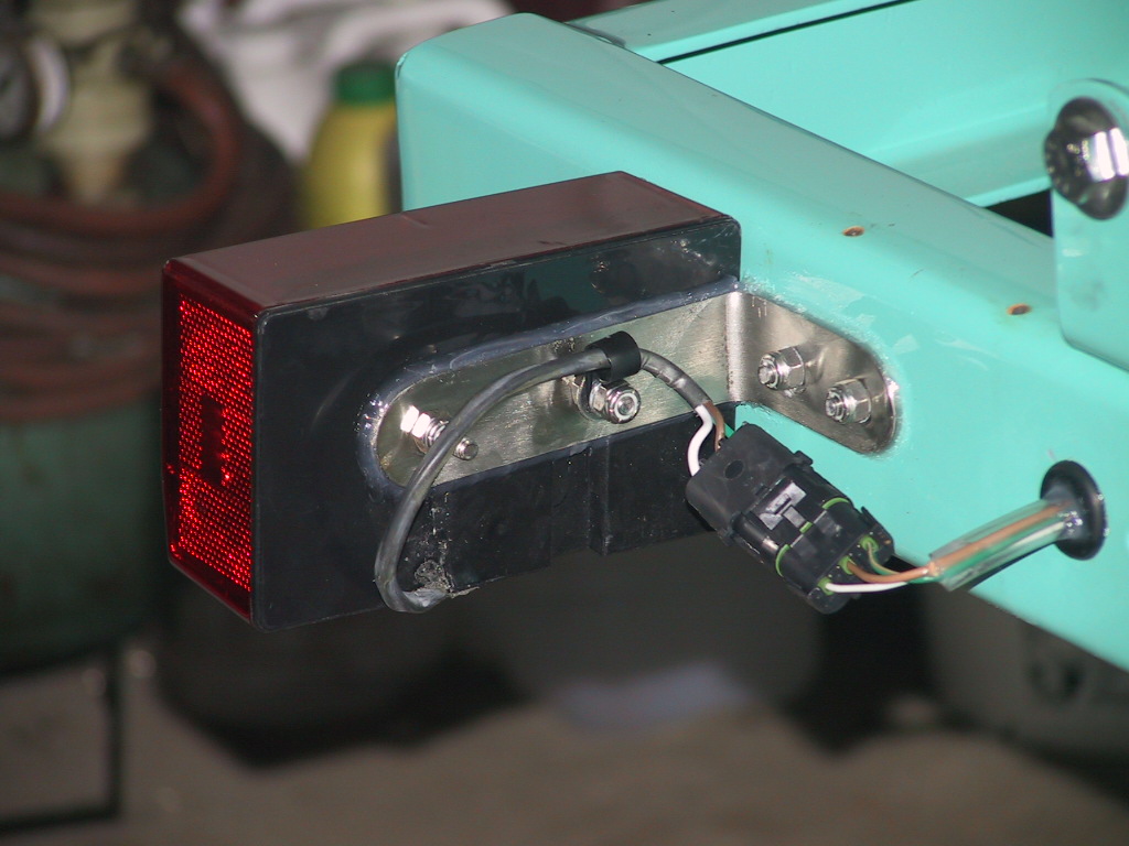
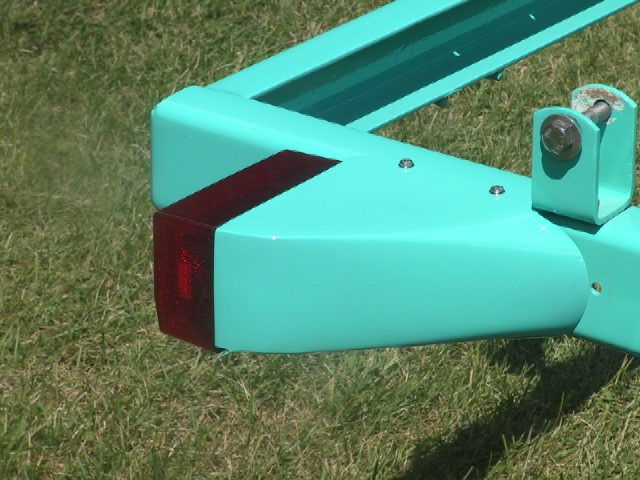
Each side harness was then routed along the top inside corner of its respective frame member and bonded to the painted surface. Where necessary to penetrate a frame rail, grommets were used to protect the pvc tubing and to seal off the bare metal where the hole was drilled. The taillamps will be immersed when launching and retrieving the boat so Weather Tech connectors are used to join the lamps to their respective harnesses. All lamp wiring and brackets were then covered by the lamp fairings.

The routing went across the second cross member to the side rails where it was tucked into the upper, inside corner.

The rear side routing was then taken through the rail out to the lamp mount point.

The waterproof connectors. Also note the silicone sealing where the wire exits the lamp and where the bracket attaches to the lamp and the trailer rail.

The fairing protects and hides the bracketry and the wiring.

Please Log in or Create an account to join the conversation.

Re:1963 Glastron V143 JetFlite Restoration 10 years 2 months ago #101034

  • MarkS
  • MarkS's Avatar
  • Offline
  • Moderator
  • Moderator
  • Posts: 5348
  • Karma: 118
  • Thank you received: 5
Awesome attention to detail, as always Kern. Top shelf stuff my friend!

Please Log in or Create an account to join the conversation.

Mark

Re:1963 Glastron V143 JetFlite Restoration 10 years 2 months ago #101055

Yeah what Mark said!

Bob

Please Log in or Create an account to join the conversation.

Re:1963 Glastron V143 JetFlite Restoration 10 years 1 month ago #102613

Kern, great project - the all inclusive good and bad posts are welcome as most projects I read seem to be only the high level "good only" posts. I'm working on a jetflite (70), and was wondering a few things. Like it looks like you chromed the zamak cleats and stuff but it also looks like you chromed some aluminum. Can you do that? Trying to get the shiny aluminum look (and not maintain it much). Also what was the car paint you used, pu?
Best,
Steve

Please Log in or Create an account to join the conversation.

Re:1963 Glastron V143 JetFlite Restoration 10 years 1 month ago #102814

  • Kern
  • Offline
  • Junior Boarder
  • Junior Boarder
  • Posts: 105
  • Karma: 17
  • Thank you received: 1
Hello Steve,

All the items I have rechromed to date were chromed originally.

The only aluminum parts that have been finished thus far are the windshield frame and the rub rails. Those parts have been polished only and when well done, they look similar to chrome. To maintain that look will require frequent light polishing, probably with a soft cloth and a metal polish, such as Simichrome.

I have some aluminum parts that need fill metal to be able to fit them precisely to the contours of the hull. These will be built up using aluminum filler metal heliarced to the parts where needed. They will then be recontoured as required using a die grinder. My polish/plating supplier tells me that the original and filler aluminum will polish differently so these parts will have to be chromed to provide a consistent look.

Aluminum can be chrome plated but it is not the most durable process. You can see many examples of chrome plated aluminum on car and truck wheels - primarily the high end luxury cars like Cadillac and Mercedes. Eventually the chrome will start to peel but they seem to get reasonable service from the wheels or they would not offer them.

As you may be aware, the quality of a plating job is dependent upon the initial polishing and on the layers of plating applied to the part. I found a polisher that does show quality work for the custom car market. He is not cheap but the results are much better than original.

The paint used on my boat and trailer is a PPG product. It is a non-metallic Isuzu color called Seychelles Blue. The white is a Nissan color. After color coating, all painted surfaces were clear coated.

Please Log in or Create an account to join the conversation.

Re:1963 Glastron V143 JetFlite Restoration 9 years 10 months ago #105956

  • Kern
  • Offline
  • Junior Boarder
  • Junior Boarder
  • Posts: 105
  • Karma: 17
  • Thank you received: 1
I may have mentioned previously that my wife and I are involved with a move of our household and that, combined with the cold weather, has slowed the restoration to almost a full stop. We are doing major renovations on two houses - one to prepare for sale and one to prepare for move in. I have done a few boat things which will be shown later in this narrative.

It turns out that the Glastron JetFlite was a contributing factor to the household move. My wife and I had talked about finding a new home that would get us away from the cold upper Midwest winters but had not decided where that would be. We ruled out Florida, Texas, and Arizona because of the hot summers, so we were thinking about somewhere in the middle. However, we had not determined exactly where we wanted to go for the last house we would own.

Then I started the JetFlite restoration and the realization dawned that I had always wanted to live near water for the view and access to boating. So I started searching for lake property in a band from Nashville to Kansas City. We eventually found Table Rock Lake in S.W. Missouri and found a house that met most of our criteria. The house overlooks about four miles of the lake channel, the town of Kimberling City, and the bridge. I purchased a boat slip about four miles from the house for a pontoon or deck boat and there is a public launch ramp also about four miles away. The Glastron will be kept at the house in indoor storage and will be taken to the water when desired.

The view looking east from the great room windows. Kimberling City is just left of the bridge. The nearest water is 1/2 mile and the farthest is 4 miles. The elevation above the water is 300-400 feet.

So the boat restoration was a significant factor in the path of this major life change.

Back to the restoration. A few more of the parts were picked up at the polisher/plater. Among these were the various molding parts for the console. The cross section of these moldings was rather small and did not lend itself to easily adding some type of mechanical attachment. They were bonded to the console with clear silicone seal. I have used silicone seal in the past to bond trim to the boat and cars with good results.

The console is now finished and is shown on the attached pictures. I feel that it is a significant improvement in appearance and function as compared to the original.


The finished console with the chrome moldings in place.

Another view with the lid partially opened.
Attachments:

Please Log in or Create an account to join the conversation.

Re:1963 Glastron V143 JetFlite Restoration 9 years 1 month ago #117356

  • Kern
  • Offline
  • Junior Boarder
  • Junior Boarder
  • Posts: 105
  • Karma: 17
  • Thank you received: 1
The JetFlite is finally at its new home in Kimberling City, MO. We have been busy on the house so it has not yet received any further work. During the move it served as a utility carrier for many of the items that the movers could not carry legally, such as the welding tanks. It was quite heavily loaded and slight damage to the trailer occurred. Just another addition to the task list.

With our proximity to Table Rock Lake, I purchased a dock slip and a Rinker Flotilla deck boat for use during family and guest outings. It is proving quite enjoyable and I have spent more time on the water in the past several weeks than in the previous 25 years in Illinois. Gasoline prices are also considerably less down here, making boating less costly.

Please Log in or Create an account to join the conversation.

Re:1963 Glastron V143 JetFlite Restoration 9 years 2 weeks ago #117983

  • Kern
  • Offline
  • Junior Boarder
  • Junior Boarder
  • Posts: 105
  • Karma: 17
  • Thank you received: 1
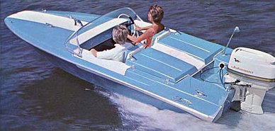
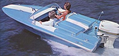
I do not believe that I have posted a theory that I have regarding the styling of the 1963 JetFlite. My theory is that the addition of the tonneau covers to the hull was inspired by the 1962 Ford Thunderbird Sports Roadster. The Thunderbird was a four seat car with an optional tonneau cover that fit over the rear seats and made it look like a two seat sports car. The cover was removable for use when the back seat was needed.

Likewise, the tonneau covers of the JetFlite are removable for those times when more than two people are in the boat.

I tried calling Bob Hammond, who started Glastron, to see if he could confirm or deny this theory. His telephone number has been disconnected so I do not know if he is still alive or has been moved to a care facility. The last information I was able to find showed his age at 87.
Attachments:

Please Log in or Create an account to join the conversation.

Time to create page: 0.393 seconds

Donate

Please consider supporting our efforts.

Glassified Ads

1956 Lonestar Meteor
( / Boats)

1956 Lonestar Meteor
12-24-2024

Mercury outboard
( / Engines)

noimage
11-03-2024

Classic Mercury Outboard Motors
( / Engines)

Classic Mercury Outboard Motors
10-18-2024

FG Login

FiberGoogle

Who's Online

We have 6082 guests and no members online